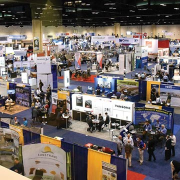
|
A Primer on Damper Technologies for Regenerative Thermal Oxidizers
By Anu Vij
Regenerative Thermal Oxidizers (RTOs) are commonly used for controlling VOC
emissions from a broad spectrum of industries. A RTO is basically a thermal
oxidizer that uses ceramic media as the heat exchanger medium, providing high
heat recoveries. Many variations of this technology are offered by RTO vendors,
which broadly fall under three categories: odd canister designs; even canister
designs; and single canister designs.
Over the past few years, much attention has been given to the pros and cons
of the different type of ceramic media used in a RTO system. However, other
critical aspects of the RTO system (viz. dampers, burners, etc.) have not been
widely covered.
Overview of RTO Damper Technologies
The purpose of valves (or dampers) in a RTO system is to provide tight shut
off of process air in order to maintain destruction and removal efficiency (DRE)
and proper heat exchanger operation (Thermal Energy Recovery or TER). Valves
serve not only to regulate the flow of air, but also to isolate ducting and
equipment for maintenance without interrupting other connected units. Valve
designs should take into account maximum system pressure, temperature changes,
and stresses imposed by the connecting ducting so as to prevent distorting and
misaligning the sealing surfaces. The sealing surfaces should be of such material
and design that the valve will remain tight over a reasonable service period.
Proper valve design is critical for high VOC destruction efficiency over a long
equipment life. Cycling more than 400,000 times a year, RTO valves must operate
reliably, and must seal to less than 0.25 percent leakage at full system pressure.
Generally two kinds of dampers are used in RTO systems. The dampers directly
connected to the RTO heat exchanger canister that direct the flow of process
air into and out of the canisters, are called the high cycle dampers because
they need to open and close every few minutes on a continuous basis. Most other
dampers associated with a RTO system are called standard duty or low cycle dampers
due to their lower cycling freq¬uency. Examples of the low cycle dampers
are isolation dampers, diverter dampers, etc. The discussion below pertains
to the high cycle valves, which are critical to the overall performance of the
RTO, namely that of achieving high destruction efficiencies. Figure 1 depicts
a typical three-canister RTO with the high cycle inlet, outlet and purge valves.
RTO designs can generally be classified into three categories: single canister,
odd canister, and even canister designs. While the odd and even canister designs
warrant traditional butterfly or poppet dampers, the single canister design
involves an entirely different technology called the rotary single can valve.
Some commonly available damper designs include:
- Butterfly Dampers (most common):
• Single Blade dampers;
• Dual Blade dampers; and
• Dual Seat dampers.
- Poppet Dampers:
• Single poppets;
• Dual poppets; and
• Four-way poppets
- Single Can Rotary Valve.
Other important issues to consider in selecting dampers for RTO applications
are:
- Valve Actuation:
• Hydraulic;
• Pneumatic; and
• Electric.
- Metal-to-Metal seats v/ tadpole seats;
- Leakage Rates (0 percent to 1 percent);
- Material of construction; and
- Resistance to condensable organics and other particulates.
Butterfly Dampers
Butterfly dampers have been applied to RTO’s for more than 30 years and
basically consist of a flat plate inserted in a gas stream. It is rotated by
means of a motor and linkage (often called an actuator) in order to control
the gas stream flow. When the damper is in the closed position it almost completely
blocks gas flow. When it is in the fully open position, the flat plate is aligned
with the direction of gas flow, and therefore, provides very little flow restriction.
Butterfly dampers occupy less space than any other valves, and have broad versatility
by the virtue of its design. They are relatively tight sealing without excessive
operating torque requirements. They offer simple and reliable means for both
modulating and on-off type of applications. A typical single blade butterfly
damper is shown in Figure 2.
Butterfly dampers employ a center mounted rotating disc or discs that typically
rotate 90 degrees for opening or closing. The solid rotating disc (generally
round shaped) must resist thermal and mechanical deformations. The type and
size of the damper dictates the torque requirements and by extension, also the
actuation requirements (e.g. beyond a certain torque, pneumatic actuators become
less desirable than hydraulic dampers due to their size).
Butterfly dampers used in the RTOs are on-off type with two designs variations:
- Single-blade damper (as shown in Figure 2) is the most common type used
in the industry. It consists of the single solid disc (“blade”)
which seats against a metal or compressible bulb (tadpole) seal; and
- Double-blade damper (shown in Figure 3) is used when “zero”
leakage is required, usually in applications where very high destruction efficiencies
are desired. Double-bladed dampers are also supplied with either a metal or
a tadpole seat. Figure 6 shows butterfly damper seating arrangements.
Figure 4 and 5 provide a schematic of the single blade and double blade dampers,
respectively. The leakage across the valve occurs when the blade is completely
shut off. On one side of the blade is contaminated VOC stream, while on the
other side is the purified air that is exiting the RTO. Thus leakage from high
VOC stream into the purified stream directly affects the overall destruction
efficiency of the RTO. Lower leakage results in higher destruction efficiency.
By employing double-blade dampers, the leakage of the VOC from one side of the
valve to the other can be completely eliminated by purging the gap between the
two blades using a fresh air, such that any leakage across the blade consists
of VOC free air.
Another butterfly damper developed more recently provides zero leakage without
requiring two separate discs. This damper, which is kind of a hybrid of the
single blade and double dampers, is called a dual seat damper because it uses
two metal seats, and achieves the performance of the double blade dampers with
the single blade configuration. The gap between the two seats is purged using
fresh air, thus achieving zero leakage. Figure 6 shows a dual seat damper seating
arrangement.
Poppet Dampers
Poppet dampers have been applied to RTO’s for over 15 years and consist
of a flat circular plate that is raised or lowered typically by an electrical
or pneumatic actuator. When the flat plate is in the closed position, it provides
a gas seal by pressing against a seat shaped like a short cylinder. Gas attempting
to pass through the cylinder is blocked. When the damper is open, there is a
one to two foot gap between the flat plate and the cylinder opening. Poppet
dampers are used for on-off control only; they are not appropriate for modulating
applications.
Poppet valves were initially developed for service in fabric filter systems
or bag houses and later applied to Regenerative Thermal Oxidizers (RTO). Fabric
filter systems require 2-way service with poppets either open or closed. System
outlet poppets are single disc low-leak models. System bypass poppets are zero-leak
and employ double blade and seat with seal air. These valves range in size from
20 inches to 47 inches diameter for industrial bag houses and 48 inches to more
than 96 inches in diameter for power generation bag houses.
Poppets for RTO service are more complex in that they seal multiple gas paths
while diverting gas in different directions. Figure 7 illustrates a 2-way poppet
for RTO service. RTO systems that are designed with 2-way poppets should have
one inlet and one outlet damper providing fail safe conditions during power
outages and upset operating conditions.
Poppet dampers of this type are driven with pneumatic or hydraulic cylinder
actuators for high-cycle service and low-leakage isolation. Hydraulic cylinders
provide the most reliable type of drive for service where 400,000 cycles per
year are expected. Poppets of this type operate best when oriented vertically.
They are available with zero-leak blades and seats as well.
Poppet valves with 3-way and 4-way configurations have also been used in RTO
systems. A 3-way poppet has one inlet and two outlets. It cycles between two
seats and diverts flow through one while sealing the other and visa versa. A
4-way poppet has two inlets and two outlets, and has been used in compact RTO
systems. Figure 8 illustrates a small 4-way poppet with two cylinder actuators
in a vertical orientation.
Single Canister Rotary Valve
The single canister rotary valve design eliminates the need for separate inlet,
outlet and valves, and replaces them with a single large valve. Rotary valve
designs have been applied to RTO’s for over 10 years. The sequence of
the bed function as an inlet, outlet or purge is achieved by the rotation of
this single valve. This valve is located below the heat recovery chambers and
is either electrically or pneumatically driven. The rotation of the valve (or
the distributor) continuously controls the air flow from inlet plenum to one
half of the heat exchange media through the retention chamber out through the
other half of the heat exchange media and then out through the outlet plenum.
The cylindrical canister holds multiple heat recovery chambers. The air is
cycled through an inlet chamber for preheating then an outlet chamber for reheating
the heat exchanger bed before exiting. Before chambers switch from inlet to
outlet flow, they are purged of any residual unoxidized gas. This purging insures
minimal VOC spikes, and maximizes destruction efficiency.
The single valve moves at several minutes per rotation and insures a smooth
transition from inlet to purge to outlet, therefore reducing upstream pressure
fluctuations which are more typical with traditional RTO designs. The single
valve also requires less maintenance compared to the multiple valve RTO system.
However, the single canister rotary valve utilizes machined metal to metal
surface to achieve tight sealing. This makes it more susceptible to wear and
tear. This seating arrangement also makes the single can RTOs more susceptible
to particulate contamination resulting in loss performance over time due to
inorganic particulate wearing on the machined metal to metal surfaces. The compact
single canister design also makes it more difficult and expensive to maintain.
References:
1. Menardi Filtration Glossary, web page
2. Perry’s Chemical Engineering Handbook, Sixth Edition
3. Ron Maxwell, Senior Flexonics/Pathway, Personal Correspondence, 2006
4. Effox Product Literature and Personal Correspondence, 2006
Anu Vij holds a B.S. in chemical engineering and a M.S. in chemical engineering
from the University of Southern California. He has fifteen years experience
as an engineer and project manager in the air pollution equipment fields. Anu
has been with Pro-Environmental since the company’s inception and now
serves as operations director. Pro-Environmental in Rancho Cucamonga specializes
in air abatement and plant process emissions control. Anu Vij: 909.989.3010;
www.pro-env.com.
|